


Customer Credentials
The customer is a leading North American specialty vehicle manufacturer engaged in the design and production of advanced ambulance and emergency response vehicles. The organization serves various emergency service providers and government agencies, requiring customized vehicle solutions that integrate medical modules with commercial truck platforms.
The customer regularly develops multiple ambulance configurations involving OEM truck chassis platforms, integrated front cabin designs, rear medical box assemblies, customer-specific layouts, and various equipment configurations.
As customer expectations evolved, the organization began exploring improved visualization methods to support both engineering activities and client discussions. Traditional 2D layouts had long been used for concept presentations; however, increasing demand for faster design decisions and enhanced customer communication created a need for more effective visualization tools.
MN Engineering Solutions (MNES) partnered with the customer during the development of a fully integrated ambulance concept that combined the front OEM cabin with the rear medical module. What initially appeared to be a CAD performance issue ultimately became an opportunity to redefine how engineering models could support both technical development and business decisions.
Situation / Challenge
The project involved developing a fully integrated ambulance assembly consisting of two major systems: the OEM front cabin assembly and the rear ambulance body assembly. The objective was to create a complete vehicle model that would support engineering activities while also enabling customer-facing presentations. However, several challenges emerged during development.
Limited OEM Data Availability meant the complete OEM front cabin model was not available. The available data sets were incomplete and required integration with the rear medical box assembly. This created difficulties in maintaining both geometric accuracy and model efficiency.
As the ambulance body components, chassis data, and cabin geometry were integrated, the assembly size increased significantly. The consequences included large file sizes, slow opening times, extended rebuild durations, reduced CAD performance, and difficult navigation within assemblies.
The heavy assembly negatively affected engineering efficiency. Design teams experienced delayed design iterations, reduced responsiveness during modifications, longer waiting periods during regeneration, and lower productivity during development activities.
The customer also had an additional expectation: the integrated ambulance model needed to be sufficiently presentable for customer discussions, concept reviews, sales presentations, and internal decision-making. Historically, these activities relied primarily on 2D layouts. The project therefore required a model that could satisfy both engineering and presentation needs.
This transformed the problem from a simple CAD performance issue into a broader challenge involving usability, visualization, and business effectiveness.
Implications
The growing assembly size created implications across multiple functions.
Engineering Implications
Heavy CAD models significantly reduced engineering efficiency. Engineers experienced longer opening times, slower regeneration cycles, increased system resource consumption, and reduced modeling productivity.
Design modifications that should have taken minutes often required considerably more time due to software performance limitations.
Collaboration Challenges
Large files also affected collaboration. Team members faced difficult file sharing, slower data transfers, increased workstation requirements, and reduced accessibility across teams.
As multiple stakeholders became involved, the model became increasingly difficult to manage.
Client Communication Limitations
Traditional 2D layouts lacked the visual impact needed for modern customer discussions.
The inability to effectively demonstrate vehicle concepts through interactive 3D visualization limited customer understanding, design discussions, decision-making speed, and sales effectiveness.
Project Timeline Risks
Performance issues increased the risk of delayed concept approvals, longer development cycles, reduced engineering bandwidth, and potential schedule impacts.
The organization required a solution that balanced engineering requirements with practical usability.
Solution Implemented by MNES
Rather than continuing with conventional modeling practices, MNES reassessed the fundamental purpose of the assembly. The key question was: "What should this model accomplish?" The answer identified three primary objectives: lightweight performance, visual accuracy, and effective communication.
Optimized Geometry Representation
Instead of maintaining unnecessary detail throughout the entire assembly, geometry representation was optimized according to functional requirements. Critical design areas retained their required accuracy, while non-essential details were simplified. This reduced the computational burden without compromising design intent.
Intelligent Representation of OEM Data
Special attention was given to the front cabin and chassis data. Since complete OEM information was unavailable, MNES restructured how available geometry was represented within the assembly. The approach focused on essential interface geometry, functional integration requirements, visual appearance, and packaging considerations. This significantly reduced unnecessary model complexity.
This transformed the modeling philosophy from:
Reduction of Computational Load
The assembly architecture was redesigned to improve overall system performance. The optimization strategy included simplified representation techniques, improved assembly organization, efficient component management, and controlled detail levels. The resulting model became substantially easier to open, manipulate, and regenerate.
Maintaining Visual Fidelity & Enabling Client-Facing Applications
Visual Accuracy
While reducing complexity, maintaining visual accuracy remained a priority. The optimized model continued to provide realistic vehicle appearance, accurate packaging visualization, effective concept communication, and reliable design validation.
This balance between performance and appearance proved critical.
Client-Facing Applications
For the first time, the organization could use 3D vehicle models during customer presentations, sales discussions, design reviews, and concept evaluations.
The model became both an engineering asset and a business communication tool.
Outcome
The project delivered measurable benefits across engineering, collaboration, and customer engagement activities.
Quantitative Improvements
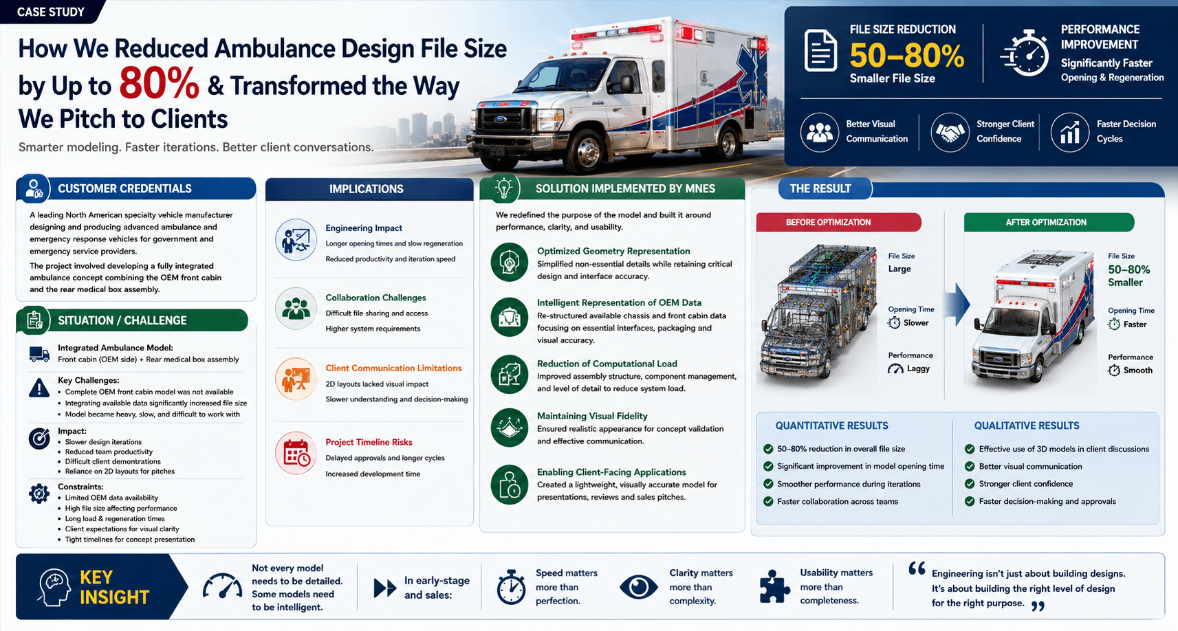
The optimization efforts produced several measurable results. The majority of these improvements were achieved through the optimized representation of OEM chassis and front cabin assemblies.
- 50–80% reduction in overall assembly file size
- Significant reduction in model opening times
- Faster assembly regeneration
- Improved workstation performance
- Reduced computational requirements
- Faster design iterations
- Improved collaboration efficiency
Qualitative Improvements
Improved Engineering Efficiency
Design teams could now modify assemblies more quickly, navigate large models smoothly, reduce waiting times, and improve overall productivity. Engineering resources could focus more on design activities and less on software limitations.
Better Client Communication
One of the most significant outcomes was the ability to use 3D models during customer discussions. This created better visualization, improved customer understanding, faster decision-making, and increased confidence in proposed concepts.
Enhanced Sales Support
Sales teams benefited from visually realistic concepts that improved communication during proposal stages. This enabled more engaging presentations, better concept validation, reduced misunderstandings, and stronger customer confidence.
Strategic Learning
The project reinforced an important engineering principle: Not every model needs maximum detail. Some models need maximum intelligence. In early-stage engineering and concept development, speed can be more valuable than perfection, clarity can be more important than complexity, and usability can be more critical than completeness.
Conclusion
This project demonstrated that optimization opportunities often exist beyond structural design or material selection.
Sometimes the greatest improvements come from optimizing how information is represented.
By rethinking the purpose of the CAD model, MNES transformed a heavy and inefficient assembly into a lightweight, visually effective, and business-friendly engineering asset.
What began as a file size problem evolved into a solution that improved engineering productivity, accelerated collaboration, enhanced customer communication, and strengthened sales presentations. The project ultimately proved that intelligent modeling can create value far beyond CAD performance—delivering both engineering efficiency and tangible business benefits.