


Customer Credentials
A leading ambulance manufacturer faced recurring challenges in managing design documentation across multiple builds. As the product range expanded to include various truck platforms, inconsistencies in drawings, part numbering, and BOM structures began to affect production efficiency and rework rates.
Challenge
Lack of Drawing Consistency
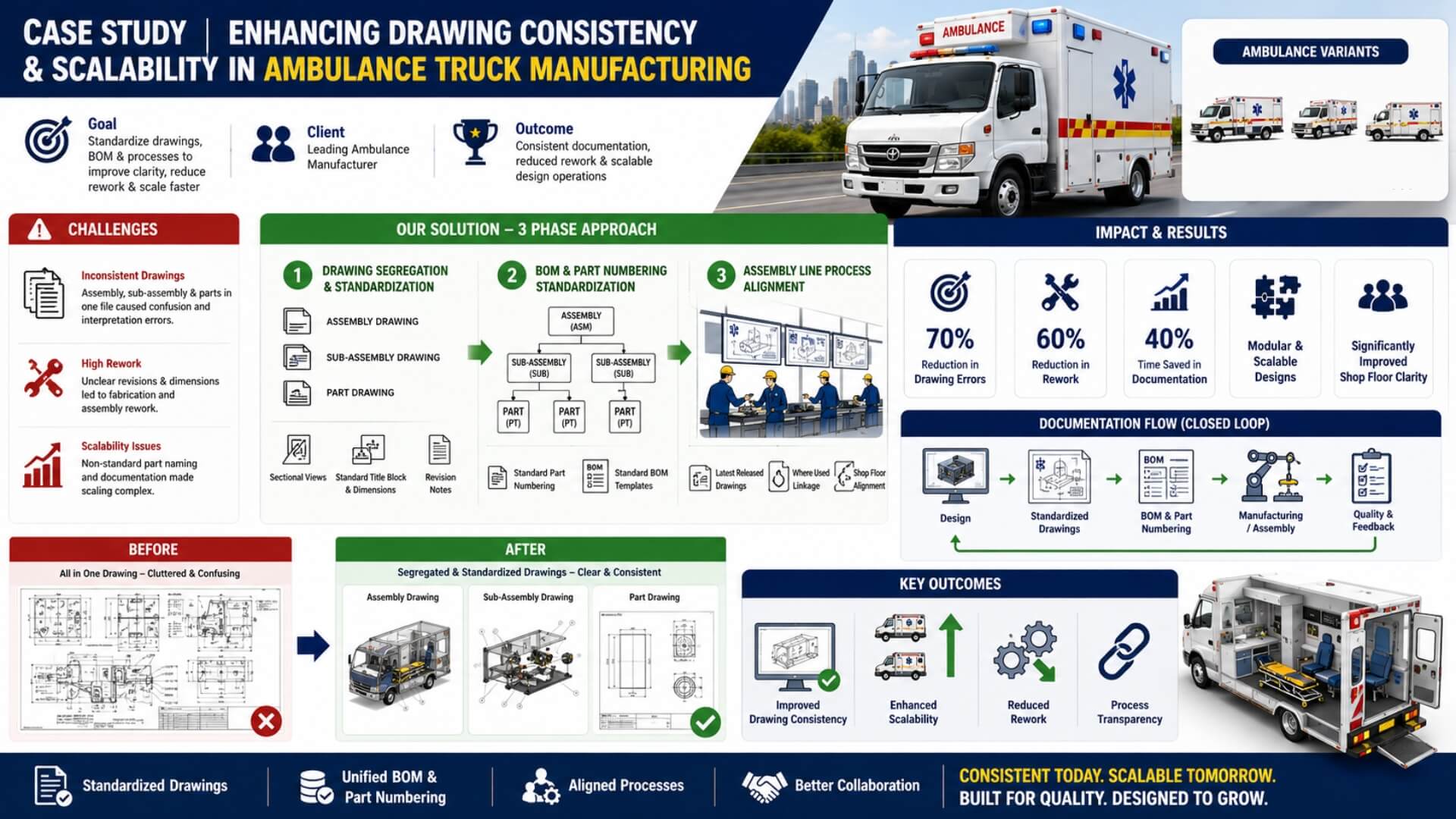
Assembly, sub-assembly, and part details were often combined in a single drawing file. This led to confusion on the shop floor, misinterpretation of dimensions, and difficulty in identifying revision impacts.
Scalability Pressure
As new ambulance variants were introduced, reusing or modifying existing drawings became increasingly complex due to non-standardized part naming and documentation practices. Scaling up design operations across teams led to version mismatches and delays in release.
High Tolerance for Rework
The absence of clear revision control and standardized BOM structures resulted in rework during fabrication and assembly. Minor design updates often required manual corrections in multiple drafts, consuming engineering bandwidth.
Solutions Implemented by MNES
Phase 1: Drawing Segregation & Standardization
All design drafts were restructured — separate drawings were created for assemblies, sub-assemblies, and parts. Sectional views were introduced in the assembly drawings to improve clarity. Uniform dimensioning practices, title block formats, and revision notes were implemented.
Phase 2: BOM & Part Numbering Standardization
A new part numbering nomenclature was established to clearly distinguish assemblies, sub-assemblies, and manufactured parts. Standardized BOM templates were created and linked to the drawing files, ensuring accurate material tracking and change management.
Phase 3: Assembly Line Process Alignment
Updated documentation standards were integrated with assembly line procedures, ensuring each workstation followed the latest released version of drawings and parts list. The team also established a "Where Used" linkage to trace component usage across multiple assemblies.
Impact and Results
| Metric | Before Implementation | After Implementation |
|---|---|---|
| Drawing Errors | Frequent cross-reference errors | Reduced by 70% |
| Rework Instances | High (due to unclear drafts) | Reduced by 60% |
| Design Scalability | Limited (manual edits needed) | Modular and scalable |
| Documentation Time | 100% manual | 40% time saved via templates |
| Shop Floor Clarity | Moderate | Significantly improved |
Key Outcomes
- Improved Drawing Consistency: Standardized templates and segregation ensured uniformity across all documentation.
- Enhanced Scalability: The structured drawing hierarchy allowed quick adaptation for new ambulance variants.
- Reduced Rework: Clear visualization and revision control minimized fabrication-level confusion.
- Process Transparency: The "Where Used" traceability and BOM alignment created a closed-loop system between design and assembly.
Before vs After – Drawing Standardization
| No. | Before (Problems Faced) | After (Implemented Improvements / Benefits) |
|---|---|---|
| 1 | Assembly, sub-assembly, and parts were all combined in a single draft, causing clutter and confusion. | Separate drafts were created for assembly, sub-assembly, and parts — improving readability and reducing confusion. |
| 2 | Sectional and detailed views were missing or unclear, making it difficult to understand part relationships. | Clear section and detail views were added in assembly drawings for better visualization of fit and alignment. |
| 3 | Frequent overlapping dimensions and unclear references due to multiple components in one sheet. | Each drawing now follows proper dimension segregation, ensuring accuracy and visual clarity. |
| 4 | Revision updates were hard to manage; changing one part required editing the entire combined draft. | Revision control simplified — updates now apply to only the affected part or assembly, improving change traceability. |
| 5 | Shop-floor teams faced frequent misinterpretation, leading to fabrication and assembly rework. | Drawings are now clearly categorized and standardized, reducing rework and improving first-time-right accuracy. |
| 6 | Lack of standard part numbering and BOM structure caused confusion during procurement and assembly. | Standardized BOM format and part numbering nomenclature implemented for uniformity and easy traceability. |
| 7 | Difficult to scale drawings for new ambulance variants due to mixed data and non-modular formats. | Modular drawing system introduced — easy to reuse or adapt drawings for different chassis and variants. |
| 8 | Assembly line lacked clarity on the latest drawing versions and part references. | Version-controlled and linked drawing templates ensure the shop floor always uses the latest approved version. |
| 9 | Communication gaps between design and production teams due to inconsistent documentation. | Documentation practices aligned with assembly line procedures, enabling smooth design-to-production flow. |
| 10 | Overall process had low drawing consistency and high tolerance for rework. | Achieved consistent documentation standards, reduced rework by over 60%, and improved production scalability. |
Conclusion
By introducing a systematic approach to drawing documentation, BOM standardization, and assembly process alignment, MN Engineering Solutions significantly improved the client's design-to-manufacturing efficiency. The initiative not only enhanced clarity and reduced rework but also built a scalable documentation framework capable of supporting future product expansion.